How to: Hovercraft
Introduction: How It Works
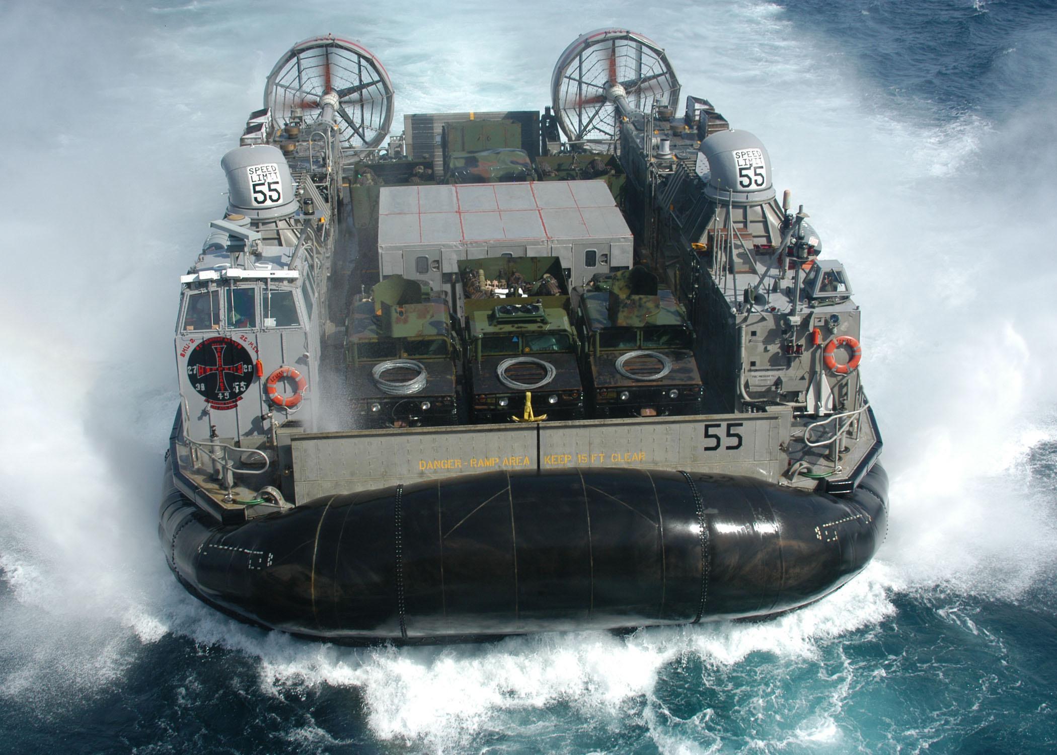
A hovercraft is a vehicle that floats a few centimeters above the ground on a cushion of air. To achieve this, a pressurized air bubble is created beneath the vehicle, usually contained by a skirt (see figure 1). This skirt can be made of flexible fabric, inflatable walls, or an air curtain maintained under pressure by a compressor. The pressurized air lifts the entire vehicle slightly off the ground, allowing it to move over the air cushion.
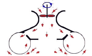
Figure 1: Principle of a hovercraft with an inflatable skirt.
Such a vehicle can move over both water and land. However, rough terrain presents challenges, as large surface irregularities can cause uncontrolled air leakage from the pressurized cushion. To address this, I explored and implemented design concepts to allow a hovercraft to safely navigate uneven surfaces. This post outlines the path I took to develop a functional hovercraft prototype.
Constraints
Prototypes were built using a Creality Ender-3 3D printer, so the vehicle had to remain small. I didn’t want to print turbines in multiple parts, so the design had to fit within a 220x220x250 mm build volume. Brushless drone motors were used for propulsion, powered initially by a 3S 1500mAh LiPo battery, later replaced with a 4S 6000mAh battery.

Figure 2: Brushless motor used for the compressor (920kv).
Part 1: The First Prototype
Each prototype is based on a turbine compressor designed to generate air overpressure. The first turbine concept was inspired by a high-pitch propeller, similar to a water turbine. When spinning, this design generates pressure on one side, creating the air cushion. Additionally, the propeller design reduces compressor noise and vibration.
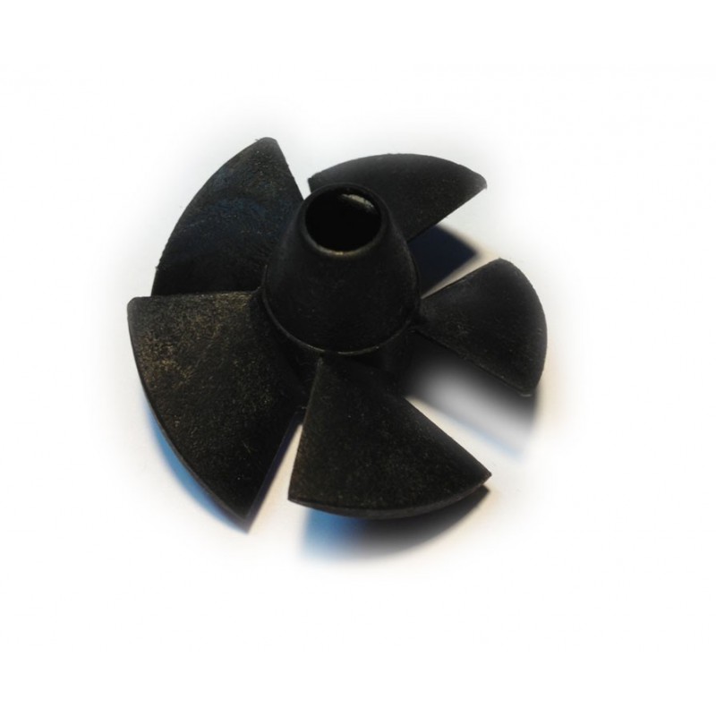
Figure 3: Turbine concept inspiration.
Blade angles were optimized to reduce support during printing, and concentric infill was used for better balance and reduced vibration at high speeds. Each turbine was encased in a tube with reinforcements to secure it.
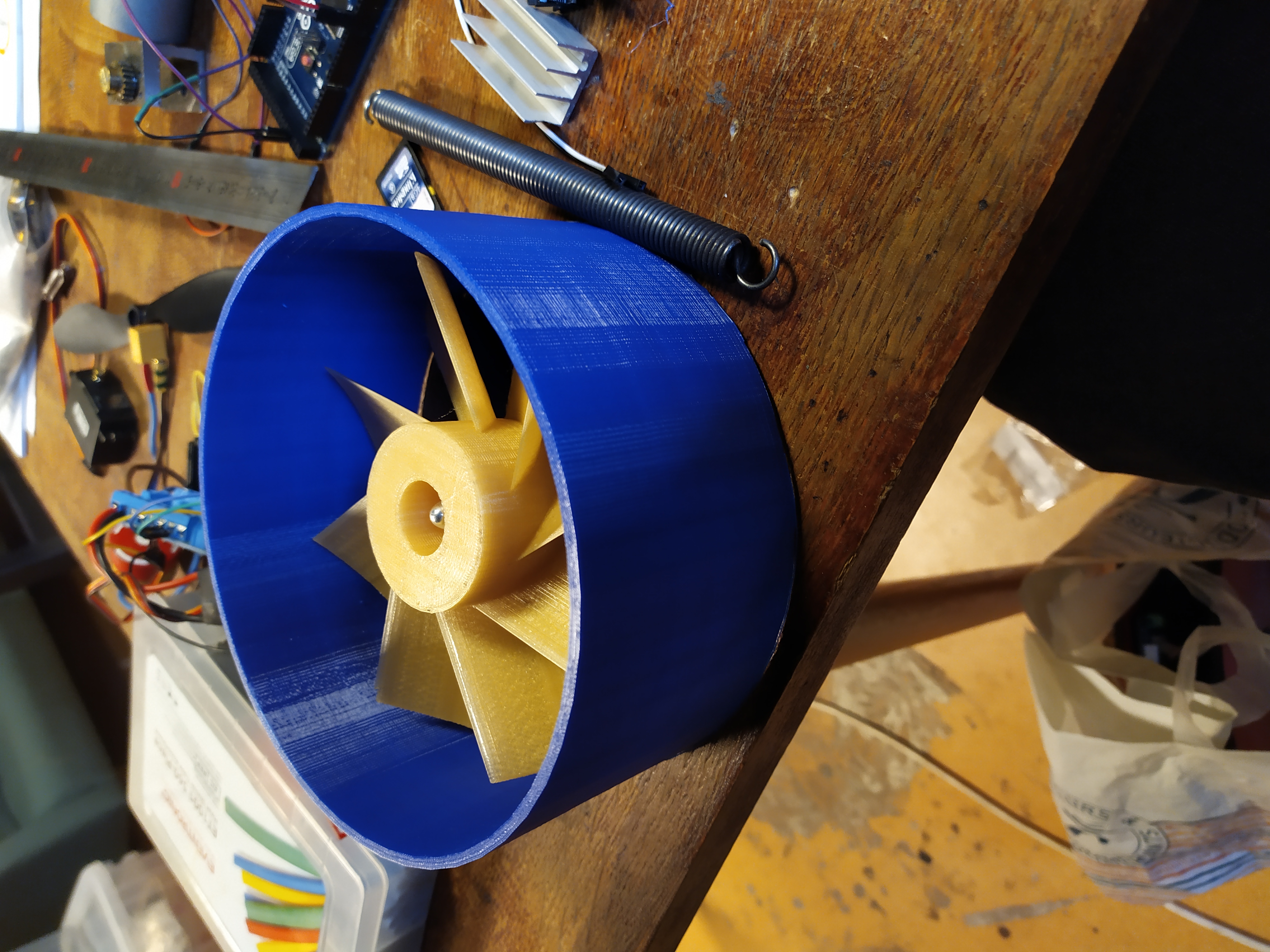
Figure 4: The first turbine.
To maintain the air cushion, a flexible, waterproof skirt made from kite fabric was used. Inflatable skirts were considered but not pursued. Initial tests were promising—the system produced strong airflow and lifted the vehicle even at 50% motor power.
Initial test, motors at 50% power.
Using a single turbine caused uncontrollable rotation due to its high inertia. To counteract this, I added four turbines—two rotating clockwise and two counterclockwise. This setup mimics quadcopter torque control.
The first prototype was tested to validate the concept:
First full-system test.
The test results were disappointing. Most energy was lost as noise, suggesting that the turbines were too large for their supports. They were also inefficient. This design was therefore abandoned.
Part 2: A Second Prototype
After the failure of the large turbine, I designed a smaller one inspired by the air turbine in figure 5.
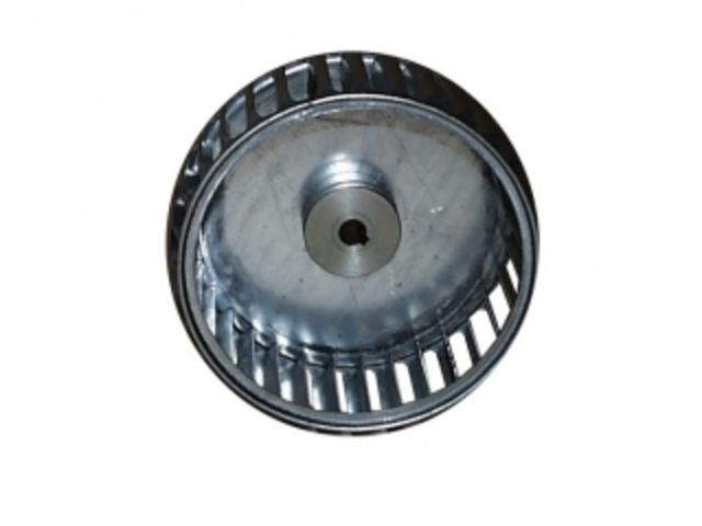
Figure 5: Air turbine inspiration.
This design was more difficult to print due to overhangs. I used bridging techniques and avoided supports for better results. The skirt was built as before using kite fabric.
Cushion Sealing
The main challenge was making the turbine housing airtight. A groove was printed into the turbine so the lid could slot into it. With lubrication, this theoretically created a seal. However, contact between the turbine and housing caused friction, compromising efficiency. I opted for a looser fit, sacrificing some sealing.
First cushion test with improved turbine.
The success of this test led to building a second, mirrored cushion so the turbines could spin in opposite directions and cancel out each other’s torque.
Startup phase with heavy vibration.
Stable operation.
System shutdown.
At high speed, the system remained stable thanks to gyroscopic effects. However, startup and shutdown were problematic due to imbalance. Increasing clearance could reduce friction but would also reduce pressure, making this unviable. So, a new design was needed.
Part 3: The Third Prototype
This version uses a pump-style turbine, easier to print and requiring no support. Sealing is done using a closely-fitting lid that rotates with the turbine, forming a pivot connection. Even with contact, there’s no risk of jamming.
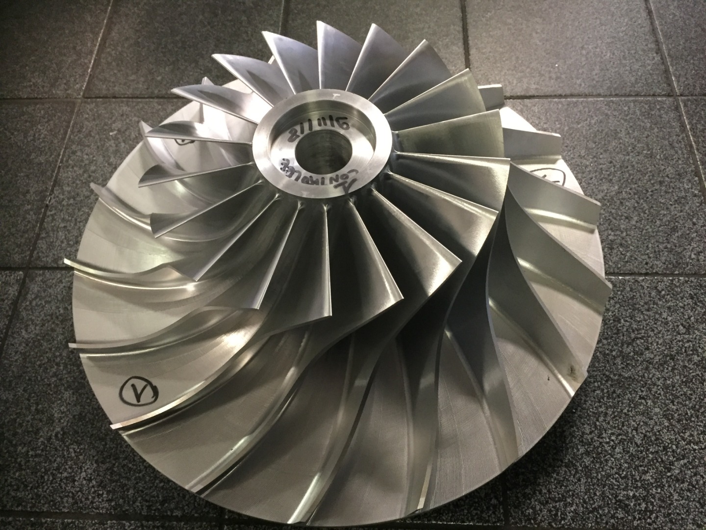
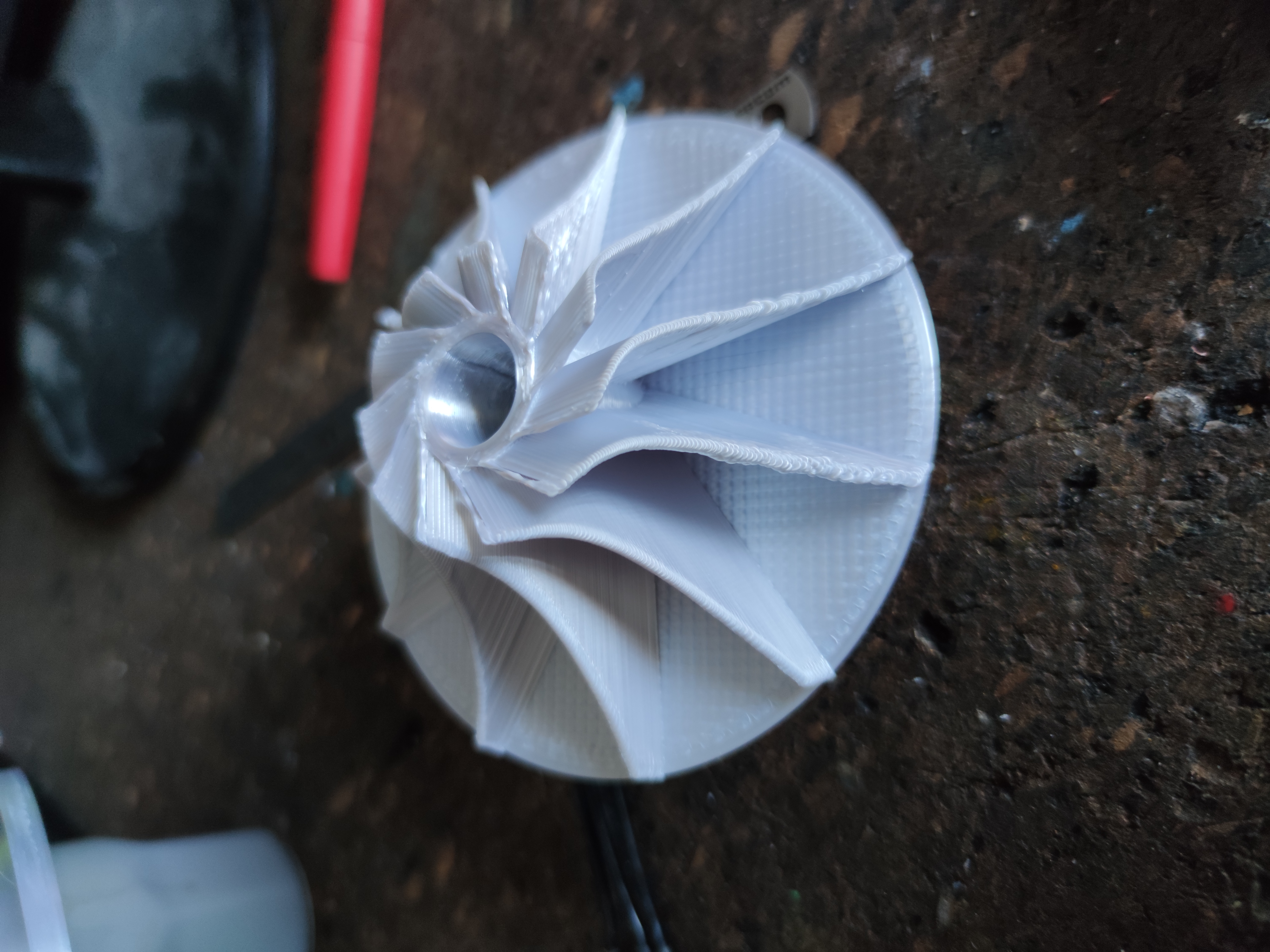
Figure 6: Pump-style turbine and its 3D-printed version.
A battery was added. Despite its weight, the hovercraft was able to float!
First test of the third prototype.
Controlling the Hovercraft
For control, a fixed propeller was added to generate thrust. Ideally, a steerable propeller would guide airflow direction.
Adding a fixed propeller.
I considered a pivoting propeller, but available motors were too heavy. Instead, I added a fixed propeller and a rudder to steer by deflecting airflow. At low speed, changing motor torque could help steer, but this proved ineffective. Ultimately, I used rudders to direct the thrust.
System in action.
Conclusion
The proof of concept works! The next step is to make the system robust, especially the cable routing, which was skipped for now.